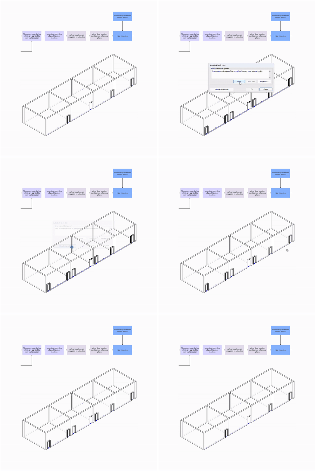
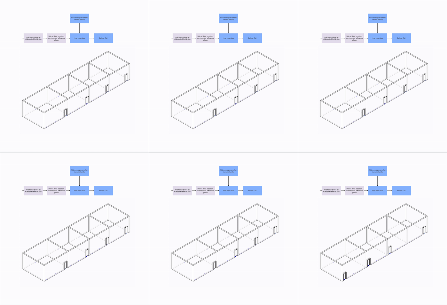
Project History: This the second part of the Penn Health Care Tool Kit. This script caters to the continued challenge of last minute design changes to entrance orientation, which changes all furnishing layout in the 3d space. More so to comply to regulations.
Automatically repositions and re-orients objects across defined boundaries while preserving adjacency rules
Challenge
In any 3D environment, large healthcare and commercial projects, whether architectural models, AR scenes, or CAD prototypes changing the position or orientation of an object often disrupts its surrounding layout. This occurred very frequently on health care projects where clients would require door placement and orientation often late in the design cycle. A simple door flip can result into hours of rework because it is linked to the furniture layouts, equipment placement, and clearances must all update accordingly. Manual updates are slow and error-prone, especially when positional offsets, orientation rules, and adjacency constraints must be maintained.
This script was built to eliminate that friction: automatically detecting target doors by room type. Then mirrors them to the opposite side of their host wall, and ensuring precise offsets from adjacent walls. This insures that doors are in proper placement and are hosted to the walls.


Process
Design rule for user: Users should define the specific room types before using the script and make sure all doors face inwards into rooms to avoid Revit API location detection errors.
Matrix
- Filter target objects based on user-defined category or metadata (e.g. room type)
- Select and mirror objects to the opposite side of their primary host surface or reference geometry.
- Maintain fixed offset between the mirrored object and its nearest adjacent geometry (e.g., constant 6″ clearance or other defined tolerance).
- Update object orientation so facing direction is consistent with the new mirrored position.
Features
- Process all objects within the active model or scene.
- Filter objects dynamically by user-defined category, type, or tag.
- Scope control: Apply per level, layer, or active view context.
- Define mirror plane: Reference plane is derived from the central boundary of the host geometry.
- Constraint-based placement: Relocated objects maintain a fixed offset from the nearest adjacent geometry (e.g., 6″ user defined tolerance).
I built this system keeping Agile work flows in mind. The system was developed in small increments, starting with a simple mirror function and then layering in offsets, orientation control, tagging, and cleanup. Each step responded to real testing feedback and was kept modular, so new rules or object types can be added easily. This way the tool stayed flexible and could evolve quickly without breaking. At each step testing was carried out to reduce errors and work through minute complexities.
Design:
System follows incremental logic, executed step by step through multiple iterations.
- Select all rooms in Active view
- Target Filtering: Filter rooms per user input
- Boundary detection: Get room finish boundaries
- Get doors of filtered rooms
- Get door and host wall information
- Get room finish boundaries close to host wall location
- Get parallel and closer room boundary


- Mirror plane generation: Create reference plane at center of finish boundary
- Relocation logic: Mirror old door location based on constraints
- Host a new door to the door location.
- Instance Tracking: Add Parameters to door family to filter old from new
- Automated Cleanup: Check if door is old or new through assigned params. If new is places delete old door.


Code

Flow Diagram

Grasshopper Script

Solution
A modular automation that reduces manual placement to a single step. It enforces strict adjacency and orientation constraints and this logic can works across different object types and environments. Since the product was developed iteratively, new constraints such as different types of doors, flipping conditions and clearances can be layered into the system.
Impact
- This prototype originated in building design however its core logic can be deployed anywhere objects need to be repositioned intelligently. That is:
- AR/VR: Adjust props or UI panels dynamically as users move in physical space.
- Robotics: Recalculate grasping/placement positions relative to a workpiece.
- CAD/Manufacturing: Mirror or reposition components while maintaining assembly tolerances.