Simulating fibrous structures with robotic precision
Challenge
The project revolves around creating a tool and framework of anchor points to weave a fibrous material using the robotic arm and rotating table. Ideally this will result in a lightweight form that can be part of an assembly making an occupiable space. This will involve testing of:
- Tool designs that focus on controlling tension and maneuverability around the frame and anchors.
- Multiple forms of frames leading to the most interesting and modular result.
- Different approaches to anchor points using hooks or bolts, finding what would most effectively work with the robots.
- Fibrous materials with different properties such as nylon string, yarn, or twine


We tested whether a robot can simulate weaving logic to produce a taut, inhabitable fibrous column without resin or chemical hardening. The project used geomtrical anchors, robotic path planning, end‑effector tension, and rotation indexing into a single workflow. The core challenge was to maintain continuous thread tension while avoiding singularity, collisions, and maintaining the tolerance drift between digital paths and the physical frame.
Context/Rationale:


Relevance and importance:
•Utility in “clean” architecture (no chemical processes)
•Lightweight components that could act as shading devices or structurally performative pieces
Implementation strategy:
To maintain the straight and firm shape of the model, giving a proper. tension of the thread is the most important. Without using resin, we should design not only the right frame and anchor but also the end of robot arm tool.
Considering the limitation of movement of the robot, we will design the path that is not disturbed by the robot itself. This path should be worked well with the turntable and supplier.
Process:

TEST:


Design:
Frame:
Whole image:


- Designed the whole model and each unit. Aggregated 3 pieces of 5′ height column-shaped models having a space to pass through.
- The aim was to connect these 3 columns together and support each on slits helping them to stand
- Each unit has a pentagon base plate on each side with hook for catching the threads. and the plates are fixed to each other with columns
Each Unit has a pentagon base plate. The base plates were produced with the assistance of the inc router, cutting the pieces from plywood as well as precisely drilling the holes for hooks to be inserted. The plates were also designed with cutouts to reduce weight as well as create a more appealing look.
The hooks are inserted and plates are fixed at a distance of 5ft from surface with 5 radially placed central columns. At this time, holes are added to the base plates to allow them to be attached to the rotating table.


During simulations we found out that robot was out of range so divided the weaving pattern into 2 portions of the column for easy accessibility.


Tool:

Received suggestions for improvements based on maintaining thread tension and thread feeding

Made suggested changes and redesigned thread tension method and thread feeding mechanism. With a spring feeder shaped like a pen, we can set the exact location of the thread feeding.

Initial tests showed that the amount of tension resulted in the spring being bent out of the intended TCP, losing the accuracy needed to reach targets.

Completed final version of the end of arm tool. Testing showed that the spool holder and feed spring provided enough tension to eliminate slack, but not too much that it bent the spring out of place.

The spring feeder was set into a solid wood base to better maintain a constant TCP.
Movement:
Connecting hooks at a long distance (vertical connection: farthest)
Robot path is configured, starting from the core and propagating outwards. From inner hook to outer hook. Separate layers of path from inside to outside


for each side
Weaving target points which were very close to the robot and the robot would reach in singularity in order to reach them so points were separated in 2 groups and their directions of planes were shifted and altered according to requirement.
Digital Model and physical model have a slightly different dimension in cutting process. Even though we measured physical model and several points, it was hard to set exact location of the path. So, we completed it with human robot collaboration. The hooks can be changed in direction manually to adjust for robotic simulation paths

Matrix Breakdown:
- Frame / Geometry: 5′ column unit; CNC‑milled pentagonal base plates with weight‑reduction cutouts; hooks positioned per anchor map; 5 radial posts; table mount points.
- Anchors: Hook orientation rules (faces out on base; faces up on column); spacing supports inside -> outside layering; clearance for tool.
- Material: Nylon/yarn/twine variants; target behavior minimal creep, consistent friction at hooks.
- Robot Kinematics: Keep toolpaths singularity‑free; avoid self‑collision + frame collision; bake safety points and tolerance offsets into the path.
- End‑Effector: Integrated spool + controlled feed; constant TCP under tension; spring‑assisted feeder to remove slack without bending out of TCP.
- Turntable: 72° index per segment; synchronize robot frames with table rotation; preserve thread continuity across rotations.
- Digital -> Physical Alignment: Compensate for fabrication tolerances; allow human–robot collaboration (manual hook tweaks) when path deviates.
- No Resin: Structure relies on continuous tension and layering density tool and sequence must sustain tautness at all times.
Features breakdown
- End‑effector evolution: v1-> v3 iterations (spool holder, pen‑style spring feeder, rigid base for TCP stability) to balance traction vs. compliance.
- Path partitioning: Weaving split into two vertical zones to keep reach feasible and minimize near‑singularity postures.
- Layering strategy: Inside -> outside layering with long‑span vertical connections scheduled when the table is optimally indexed.
- Rotational indexing: 72° steps coordinate hook access and reduce cable wrap; maintains a clean, repeatable sequence.
- Tension protocol: Feeder spring provides micro‑compliance; eliminates slack yet avoids over‑bending out of TCP.
- Human‑in‑the‑loop: Adjustable hook orientation to reconcile small dimensional drift between CAD and the real frame.
Product image:


Simulation video:
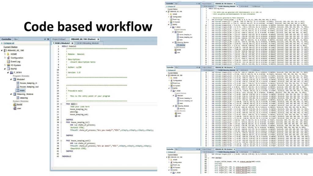
Code based workflow:

Insights:
Some flexibility in the spring not only helps maintain the taut characteristic of the thread but also helps in weaving the trad to the hooks. The flexibility helps spring adjust to new target points quickly and efficiently.
Challenges:
- Frames took longer than expected to construct so in the end we were only able to complete one frame.
- Tool rigidity and ensuring that it did not hit the frame or hooks.
- Getting the angles just right to not hit the frame as well as not giving the robot singularity errors.
- Reconciling digital model and code with the irregularities of the physical frame.
Solution:
- Physical prototype: One 5′ column unit successfully woven; continuous tension maintained without resin.
- Tooling: Final end‑effector with spool + spring feeder stabilized TCP while eliminating slack.
- Motion plan: Two‑zone strategy + 72° indexing prevented singularities and minimized collisions.
- Visual/structural effect: Layered filament with graded density; clean long‑span ties establish global stiffness. a Digital System. Grasshopper facade generator that opens/closes panels dynamically, visualized across locations and seasons.
Impact:
- Clean fabrication: No chemical consolidation; relies on path logic + tension → applicable to shading, shells, or partition systems.
- Scalable system: Column units aggregate into occupiable fields; same logic ports to different anchor typologies (frames, rings, lattices).
- Tool path intelligence: Shows how textile logics translate to robotic code—useful for education and R&D in architectural robotics.
- Future work: Multi‑robot coordination; adaptive tension sensing; closed‑loop vision for on‑the‑fly tolerance correction.
Next steps:
The hypothetical next steps would be further refining the robot movements to have even more precision, as well as constructing more frames in order to link them together into a soft structure which can be occupied..